Machine vision
Camera, lens, exposure, and trigger logic engineered around the defect—not around a catalog part.
Stable acquisition · calibrated optics · traceable imagesVision systems for autonomous local manufacturing
TNL Robotics engineers the camera, lighting, and product fixtures that turn an AI robot into a repeatable inspection cell.
Human skill, multiplied by AI robotics.
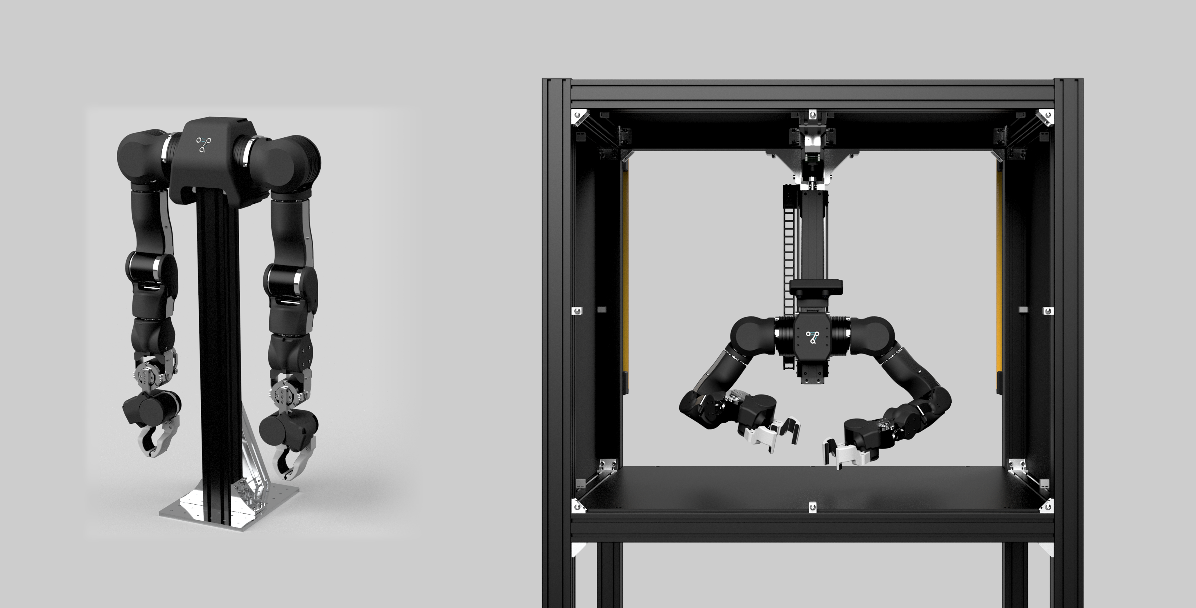 CAMERA PLANECONTROLLED LIGHTPRODUCT DATUM
OPEN ROBOT PLATFORM
CONTROLLED VISUAL EVIDENCE
REPEATABLE QUALITY DECISIONS
01 / INSPECTION SYSTEM
A model cannot recover information the physical system failed to reveal. We control the image before asking AI to interpret it.
Camera, lens, exposure, and trigger logic engineered around the defect—not around a catalog part.
Stable acquisition · calibrated optics · traceable imagesLight geometry, spectrum, and timing designed to make the relevant surface information measurable.
Exposure-synced · application-specific · serviceableJigs that constrain part pose, protect critical surfaces, and support repeatable, fast changeovers.
Datum-controlled · poka-yoke · production-ready02 / ENGINEERING METHOD
Every inspection cell is treated as a chain. A weak link in pose, light, optics, timing, or decision logic becomes a false reject—or a missed defect.
Capture the human process and the inspection decision.
Lock part pose, camera geometry, and illumination.
Turn visible evidence into a repeatable quality result.
Let the robot sort, rework, or route the product.
THE PHYSICAL AI PRINCIPLE
“Control what the camera sees before optimizing what the model predicts.”
03 / PROTOTYPE BASELINE
This reference configuration turns current engineering work into a measurable starting point. Final components remain application-dependent.
01 · IMAGING
02 · ILLUMINATION
03 · SYNCHRONIZATION
04 / DEPLOYMENT VALUE
Fixture datums and controlled illumination reduce variation before software.
Every decision can retain its image, timestamp, recipe, and model version.
Modular jigs and inspection recipes make product variants manageable.
Replaceable lights, accessible optics, and documented setup preserve uptime.
START WITH ONE PART
A useful pilot begins with part samples, a defect taxonomy, and the real line cycle time. Copy the brief and complete it with your engineering team.
No form submission. Your information stays with you.